25+ entity relationship diagram software engineering
Entity-Relationship Model ER Model is a high-level data model or a graphical approach to database design which defines the data elements and their relationship within a. Entity Relationship Diagram aka ERD ER Diagram E-R Diagram is a well-tried software engineering tool for data modeling system design and illustrating the logical structure of.
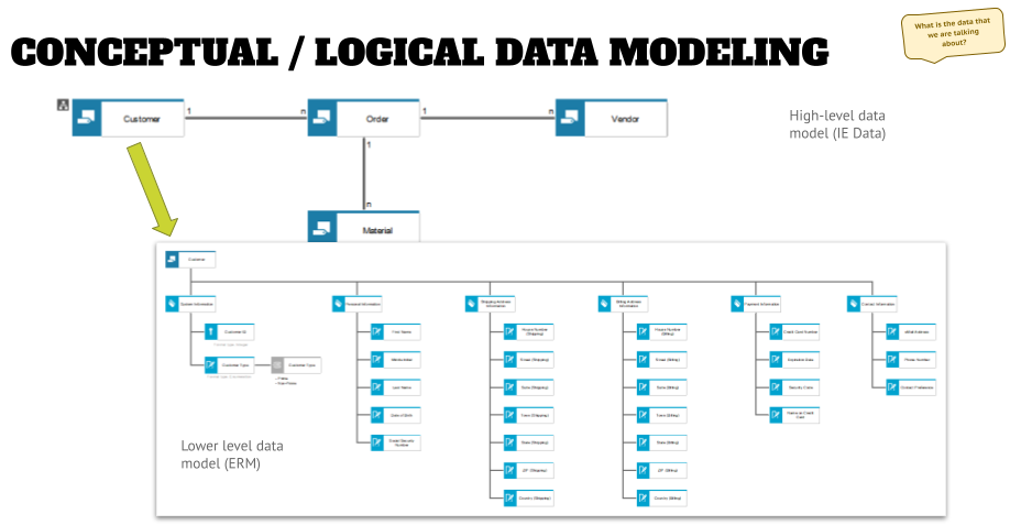
Data Models What S Your Baseline
EdrawMax is utility software for individual and businesses users.
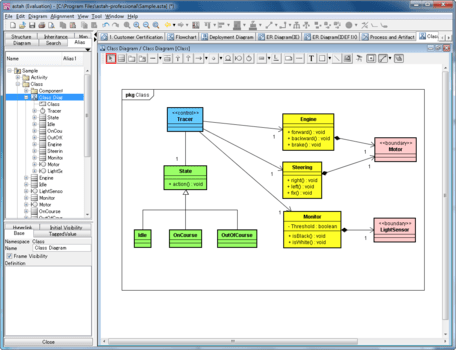
. Software engineeringentity relationship diagram. Entity relationship diagrams are used in software engineering during the planning stages of the software project. ER-modeling is a data modeling method used in software engineering to produce a conceptual data model of an information system.
Entity relationship diagrams in software engineering. Purpose of ERD See more. Entity diagrams are commonly used in software engineering.
Entity relationship diagrams are used in software engineering during the planning stages of the software project. The Entity-Relationship Model ER Model is a high information model or pictorial method to access the data architecture that outlines data pieces and their relationships inside a given. It can do over 280 kinds of diagrams including flowcharts fishbone diagrams floor plans and.
ER-modeling is a data modeling method used in software engineering to produce a conceptual data model of an information system. Diagrams created using this ER-modeling method are called Entity-Relationship Diagrams or ER diagrams or ERDs. ER Diagram stands for Entity Relationship Diagram also known as ERD is a diagram that displays the relationship of entity sets stored in a database.
An entity relationship ER diagram shows how people objects or concepts relate to each other within a process or system. A typical software system uses database. Entity Relationship Diagram aka ERD ER Diagram E-R Diagram is a well-tried software engineering tool for data modeling system design and illustrating the logical.
If you want to show which servers or devices are used for running the system you can depict it using a UML deployment diagram. The ERD was originally proposed by Peter Chen for the design of relational database systems and has been. Introduction to ERDs.
They help to identify different system elements and their. These pairs can be represented graphically using the entityrelationship diagram.
Visual Paradigm Alternatives 25 Diagram Editors And Uml Modeling Tools Alternativeto

Logical Data Models What S Your Baseline
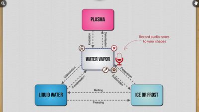
Visual Paradigm Alternatives 25 Diagram Editors And Uml Modeling Tools Alternativeto
How To Make An Entity Relationship Diagram Erd Of A Restaurant Quora
Do Ml Engineers Need To Know About Er Diagrams Quora
What Are The Best Free Online Tools To Draw An Erd Entity Relationship Diagram Quora
What Are The Best Free Online Tools To Draw An Erd Entity Relationship Diagram Quora
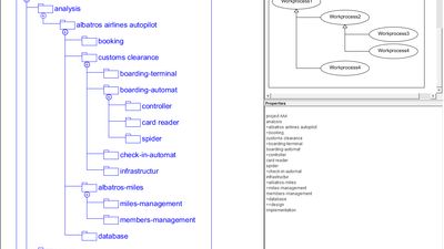
Visual Paradigm Alternatives 25 Diagram Editors And Uml Modeling Tools Alternativeto
What Are Some Good Applications To Draw Entity Relationship Diagrams Quora
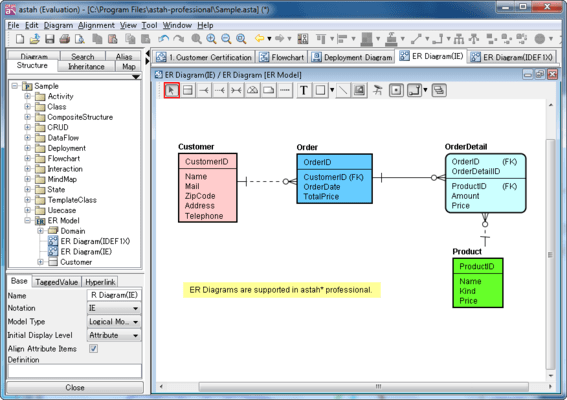
Er Diagram Entity Relationship Diagram

Astah Professional
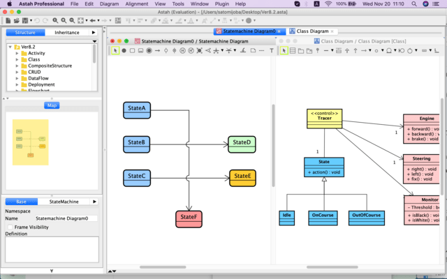
Astah Professional
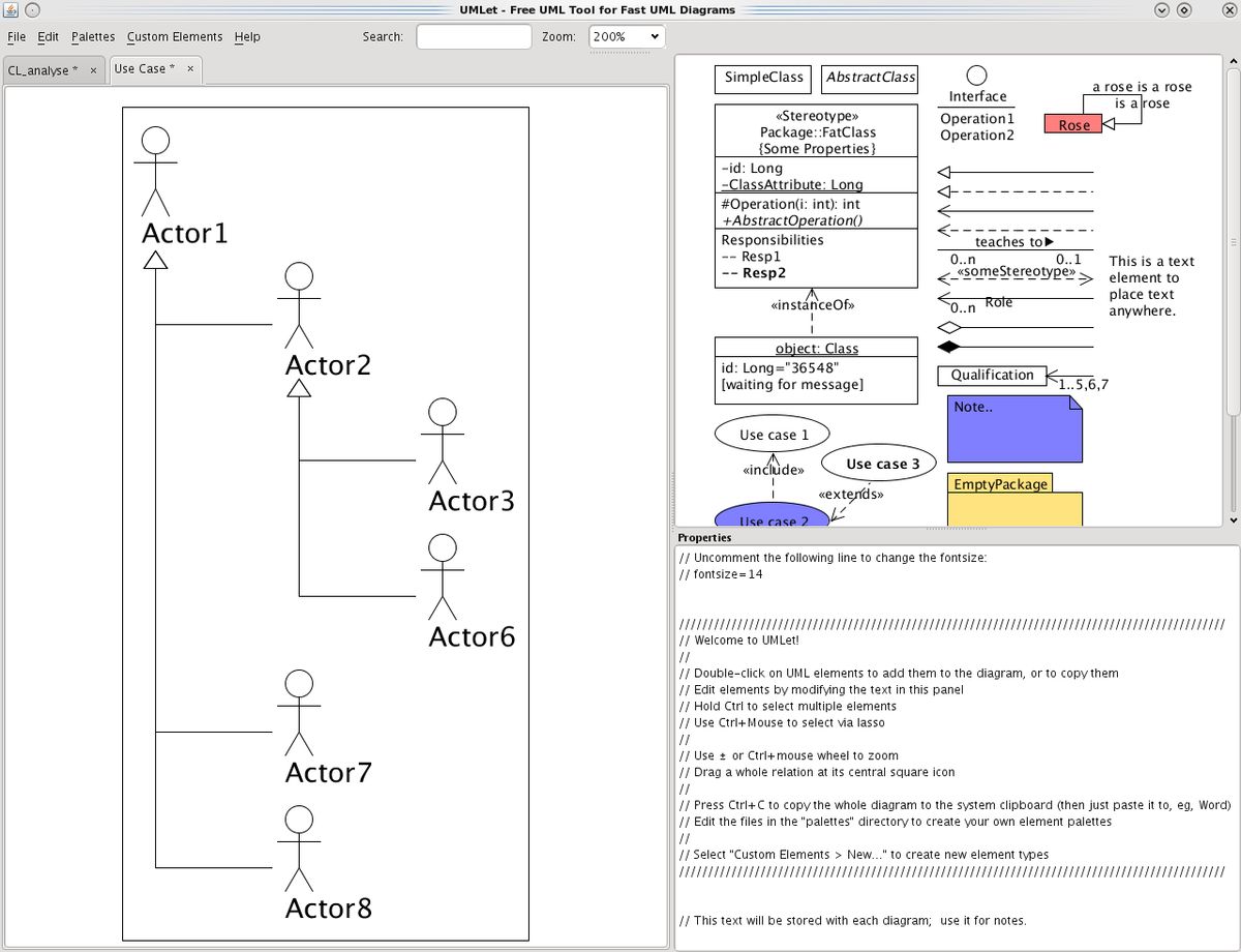
Visual Paradigm Alternatives 25 Diagram Editors And Uml Modeling Tools Alternativeto

What Is The Entity Relationship Model Diagram Examples Video Lesson Transcript Study Com

Data Flow Diagram Template Mural
How Is Cardinality Written In An Er Diagram Quora
What Are The Best Free Online Tools To Draw An Erd Entity Relationship Diagram Quora